
Uvod
This manual provides comprehensive instructions for the Generic PWM150 Programmable Dual-Channel Signal Generator. This device is designed for precise control of frequency, duty cycle, and phase, making it suitable for a wide range of applications including electronics laboratories, industrial automation, educational training, and DIY projects.
The PWM150 features independent dual-channel control with phase linkage, a clear dual-screen display, and multiple LED indicators for intuitive operation. Its compact and portable design ensures ease of use in various environments.
Sigurnosne informacije
Prije upotrebe uređaja pročitajte i razumite sve sigurnosne upute. Nepoštivanje ovih uputa može uzrokovati strujni udar, požar ili oštećenje proizvoda.
- Provjerite je li napajanje voltage je unutar navedenog raspona (5-24 VDC).
- Ne izlažite uređaj vlazi ili ekstremnim temperaturama.
- Izbjegavajte kratki spoj na izlaznim terminalima.
- Ne pokušavajte rastavljati ili modificirati uređaj. Za sve servisne radove obratite se kvalificiranom osoblju.
- Držite uređaj dalje od zapaljivih materijala.
Proizvod gotovview
The Generic PWM150 is a compact and versatile signal generator. Below is an illustration of its main components and controls.

Slika 1: Ispred view of the PWM150 Signal Generator with labeled controls and indicators. Key components include the rotary encoder, MOD, SYNC, SET, and OUT buttons, dual digital displays for frequency and duty cycle/phase, and LED indicators for channels (CH1, CH2) and output (OUT).
- Rotacijski koder: Used to adjust parameters. Press briefly to switch between digit positions (with flashing indication). Rotate to adjust the selected parameter value.
- MOD Key: Switches between channels (CH1/CH2) or changes the duty cycle/phase display in synchronous mode.
- Gumb SYNC: Enables dual-channel parameter synchronization and supports frequency, duty cycle, and phase linkage adjustment.
- Tipka SET: Accesses system settings (Power-on Output, Parameter Saving/Retrieval, Frequency/Duty Cycle Upper/Lower Limit Settings).
- OUT Key: One-click start/stop PWM signal output. A green LED indicates the output status.
- CH1/CH2 LEDs: Indicate the currently selected channel.
- IZLAZNA LED: Indicates if the output signal is active.
- Digitalni zasloni: Show frequency (in kHz) and duty cycle (in %) or phase (in °).
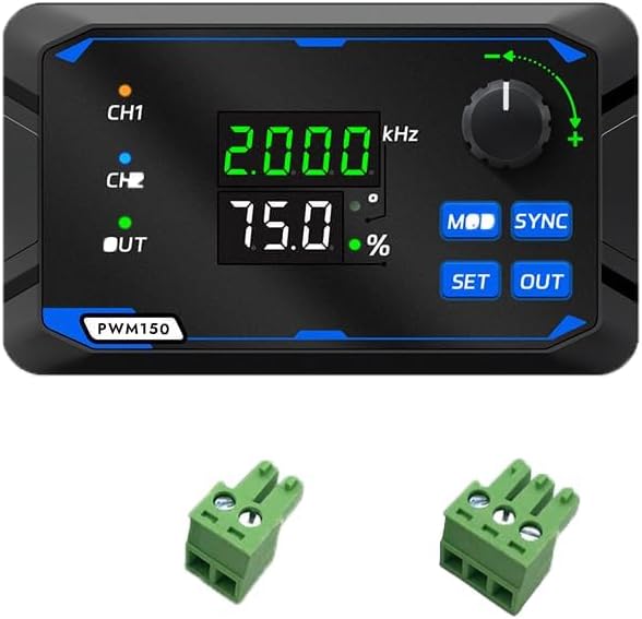
Slika 2: Odozgo prema dolje view of the PWM150 Signal Generator, showing the two green screw terminal connectors for output signals.
Tehnički podaci
| Značajka | Specifikacija |
|---|---|
| Naziv proizvoda | Programmable PWM Signal Generator |
| Marka | Generički |
| Broj modela | 0E2ATSVAM2UK42AN3FJ8 |
| Dimenzije | 120 mm x 80 mm x 25 mm (otprilike 12 x 8 x 2.5 cm) |
| Težina | 94 g |
| Duty Cycle Accuracy | 0% - 100%, 0.1% step adjustment |
| Vrijeme izlaska | 20 ns |
| Podešavanje faze | 0° - 360° (1° step, synchronous mode available) |
| Izlazni voltage | 5-24 VDC |
| Maksimalna izlazna struja | 0.2 A |
Postavljanje
- Raspakiranje: Carefully remove the signal generator and any accessories from its packaging. Inspect for any signs of damage.
- Priključak za napajanje: Connect a 5-24 VDC power supply to the designated power input terminals. Ensure correct polarity.
- Izlazna veza: Connect your load or circuit to the CH1 and/or CH2 output terminals using appropriate wiring. The device comes with screw terminal connectors for easy wiring.
- Početno uključivanje: Once power is connected, the device display should illuminate, showing default frequency and duty cycle values.

Slika 3: The PWM150 Signal Generator shown with its two green screw terminal connectors, which are used for connecting power and output signals.
Upute za rad
This section details how to operate the PWM150 signal generator to achieve desired output signals.
1. Basic Parameter Adjustment (Frequency, Duty Cycle)
- Odaberite kanal: Pritisnite tipku MOD key to switch between CH1 and CH2. The corresponding LED (CH1 or CH2) will illuminate.
- Podešavanje frekvencije: The upper display shows the frequency. Press the Rotacijski koder briefly. The digit position for frequency adjustment will flash. Rotate the encoder clockwise to increase frequency, counter-clockwise to decrease. Press again to move to the next digit or to confirm.
- Adjust Duty Cycle: The lower display shows the duty cycle (%). Press the MOD key again (if in frequency adjustment mode) or press the Rotacijski koder until the duty cycle digits flash. Rotate the encoder to adjust the duty cycle from 0% to 100%.
- Start/Stop Output: Pritisnite tipku VAN key to start or stop the PWM signal output for the selected channel. The green OUT LED will indicate the output status.
2. Synchronous Mode and Phase Adjustment
The PWM150 supports synchronous operation of both channels with phase adjustment.
- Enable Sync Mode: Pritisnite tipku SINKRONIZACIJA button. The device will enter synchronous mode, linking parameters between CH1 and CH2.
- Adjust Phase: In synchronous mode, the lower display can show phase (in °). Use the MOD key to cycle through duty cycle and phase display. Once phase is displayed, press the Rotacijski koder to select the digit and rotate to adjust the phase from 0° to 360° in 1° steps.
- Linked Parameters: When in synchronous mode, adjustments to frequency or duty cycle on one channel may affect the other, depending on the specific synchronization settings.
3. System Settings (SET Ključ)
Pritisnite tipku SET key to access advanced settings. These typically include:
- Power-on Output State: Configure whether the output is active or inactive upon power-up.
- Parameter Saving/Retrieval: Save custom settings for quick recall.
- Frequency/Duty Cycle Limits: Set upper and lower limits for parameter adjustments.
Navigate through the settings using the MOD key and adjust values with the Rotacijski koder. Pritisnite SET again to exit the settings menu.
Održavanje
- Čišćenje: Za čišćenje uređaja koristite meku, suhu krpu. Nemojte koristiti abrazivna sredstva za čišćenje ili otapala.
- Skladištenje: Uređaj čuvajte na hladnom i suhom mjestu, dalje od izravne sunčeve svjetlosti i ekstremnih temperatura kada se ne koristi.
- Inspekcija: Periodically check the wiring and connections for any signs of wear or damage.
Rješavanje problema
| Problem | Mogući uzrok | Otopina |
|---|---|---|
| Uređaj se ne uključuje. | Nema napajanja, neispravan volumentage, or reversed polarity. | Check power supply connection, ensure voltage is 5-24 VDC, and verify polarity. |
| Nema izlaznog signala. | Output is disabled, incorrect settings, or faulty connection. | Pritisnite tipku VAN key to enable output. Check frequency/duty cycle settings. Verify output wiring. |
| Parameters cannot be adjusted. | Encoder not pressed, or in a locked mode. | Pritisnite tipku Rotacijski koder to select a digit for adjustment. Ensure not in a menu that prevents adjustment. |
| Inaccurate output. | Incorrect calibration (unlikely for new device) or external interference. | Ensure proper grounding. If issues persist, contact support. |
Jamstvo i podrška
For warranty information, please refer to the terms and conditions provided by your retailer or contact the manufacturer directly.
For technical support or inquiries, please contact the seller through the platform where the product was purchased.
