1. Uvod
This manual provides essential information for the installation, operation, maintenance, and troubleshooting of the Juniper Networks EX4200-24P 24-Port Power over Ethernet (PoE) Ethernet Switch. The EX4200-24P is designed to provide high-performance, reliable network connectivity for enterprise and data center environments, offering 24 Gigabit Ethernet ports with PoE+ capabilities and Layer 3 features.
2. Sigurnosne informacije
Pridržavajte se sljedećih sigurnosnih mjera kako biste spriječili ozljede i oštećenje opreme:
- Osigurajte ispravno uzemljenje uređaja.
- Ne koristite prekidač u mokrim ili pretjerano vlažnim okruženjima.
- Isključite napajanje prije izvođenja bilo kakvih postupaka održavanja ili instalacije.
- Use only approved power cords and accessories.
- Osigurajte odgovarajuću ventilaciju oko prekidača kako biste spriječili pregrijavanje.
3. Sadržaj paketa
Provjerite sadrži li vaš paket sljedeće stavke:
- Juniper Networks EX4200-24P Ethernet Switch
- Kabel za napajanje
- Rack-mount Kit (brackets, screws)
- Konzolni kabel (RJ-45 na DB-9)
- Dokumentacija (Kratki vodič, Sigurnosne informacije)
Note: Contents may vary based on the specific renewed product offering.
4. Fizički overview
4.1 Prednja ploča
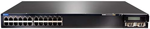
Figure 4.1: Front Panel of EX4200-24P Switch. This image displays the front of the Juniper Networks EX4200-24P switch, featuring 24 RJ-45 Gigabit Ethernet ports, each with LED indicators, and four SFP+ uplink ports on the right side, along with a small LCD display and control buttons.
The front panel of the EX4200-24P switch includes:
- 24 x 10/100/1000BASE-T Ethernet Ports: RJ-45 connectors for network devices. Each port supports Power over Ethernet Plus (PoE+).
- LED indikatori statusa priključka: Indicators for link status, activity, and PoE status for each port.
- Uplink Module Slot: Typically houses 4x SFP/SFP+ ports for high-speed uplinks to other network devices or the core network.
- LCD zaslon: Provides system status, configuration information, and error messages.
- Kontrolni gumbi: Used to navigate and interact with the LCD display menu.
- LED status sustava: Indicators for power, alarm, and system status.
4.2 Stražnja ploča

Slika 4.2: Kutno View of EX4200-24P Switch. This image provides an angled perspective of the Juniper Networks EX4200-24P switch, highlighting the front panel with its 24 Ethernet ports and uplink module, and giving a partial view of the side chassis. The rear panel, not fully visible in this image, typically contains power input, fan modules, and a console port.
Stražnja ploča obično uključuje:
- Priključak za izmjeničnu struju: Za spajanje kabela za napajanje.
- Konzolni priključak (RJ-45): For local management and initial configuration using a serial connection.
- USB priključak: For software upgrades or configuration backup/restore.
- Moduli ventilatora: Removable fan trays for cooling.
5. Postavljanje i instalacija
5.1 Priprema mjesta
Before installation, ensure the installation site meets the following requirements:
- Okruženje: Maintain an ambient temperature between 0°C and 45°C (32°F and 113°F) and relative humidity between 10% and 85% (non-condensing).
- Vlast: A dedicated power outlet with proper grounding is recommended.
- Ventilacija: Ensure at least 5 cm (2 inches) of clearance at the front and rear for airflow.
5.2 Montaža u stalak
The EX4200-24P is designed for installation in a standard 19-inch equipment rack.
- Pričvrstite priložene nosače za montažu u rack na bočne strane prekidača pomoću priloženih vijaka.
- Align the switch with the rack posts and secure it using appropriate rack screws.
5.3 Priključak za napajanje
- Connect one end of the power cord to the AC power connector on the rear panel of the switch.
- Drugi kraj kabela za napajanje spojite na uzemljenu električnu utičnicu.
- The switch will power on automatically. Observe the system status LEDs for initial boot-up.
5.4 Mrežne veze
- Connect Ethernet cables from your network devices (computers, IP phones, wireless access points) to the RJ-45 ports on the front panel.
- For uplink connections to other switches or routers, insert appropriate SFP/SFP+ transceivers into the uplink module slot and connect fiber or copper cables as required.
- For initial configuration, connect a console cable from your management workstation to the console port on the rear panel.
6. Upravljanje prekidačem
6.1 Power On and Initial Boot
Once connected to power, the switch will begin its boot sequence. The system status LEDs will indicate the boot progress. The LCD display will show system information during startup.
6.2 LED indikatori
Monitor the LEDs on the front panel to understand the switch's operational status:
- LED sustava: Indicates overall system health (e.g., green for normal operation, amber for minor alarm, red for major alarm).
- LED za napajanje: Označava status napajanja.
- Port Link/Activity LEDs:
- Stalno zeleno: Veza uspostavljena.
- Trepere zeleno: Activity on the port.
- isključeno: Nema veze.
- PoE Status LEDs: Indicate Power over Ethernet status for PoE-enabled ports.
6.3 Basic Configuration Access
The switch can be configured via the command-line interface (CLI) through the console port or remotely via Telnet/SSH after initial IP configuration. Refer to the Juniper Networks documentation for detailed CLI commands and configuration guides.
- Konzolni priključak: Use a terminal emulator (e.g., PuTTY) with settings: 9600 baud, 8 data bits, no parity, 1 stop bit, no flow control.
- Web sučelje: Some Juniper switches offer a web-based management interface. Check your specific firmware version for availability and default access details.
7. Održavanje
7.1 Čišćenje
Regular cleaning helps maintain optimal performance and extends the lifespan of the switch.
- Power off and disconnect the switch before cleaning.
- Za brisanje vanjske strane koristite meku, suhu krpu.
- Use compressed air to clear dust from ventilation openings and fan modules.
- Ne koristite tekuća ili aerosolna sredstva za čišćenje izravno na prekidaču.
7.2 ažuriranja firmvera
Povremeno provjeravajte podršku Juniper Networksa website for the latest firmware updates. Firmware updates can provide new features, performance improvements, and security patches. Follow the instructions provided with the firmware package for proper installation.
7.3 Razmatranja okoliša
Ensure the switch operates within its specified temperature and humidity ranges. Avoid blocking ventilation ports and ensure proper airflow to prevent overheating, which can lead to system instability or failure.
8. Rješavanje problema
Ovaj odjeljak nudi rješenja za uobičajene probleme s kojima se možete susresti.
8.1 Bez napajanja
- Provjerite je li kabel za napajanje sigurno spojen i na prekidač i na električnu utičnicu.
- Provjerite je li utičnica ispravna tako da u nju priključite drugi uređaj.
- Ensure the power supply unit (if modular) is properly seated.
8.2 Nema veze na portu
- Provjerite spoj Ethernet kabela na oba kraja. Pokušajte s drugim kabelom.
- Provjerite je li povezani uređaj uključen i ispravno radi.
- Check the port configuration on the switch (e.g., speed, duplex settings).
8.3 Problemi s mrežnom povezivošću
- Confirm the switch has a valid IP address and network configuration.
- Check for IP address conflicts on the network.
- Verify VLAN configurations if applicable.
- Ponovno pokrenite sklopku i povezane uređaje.
8.4 Vraćanje na tvorničke postavke
A factory reset will erase all configurations and restore the switch to its default settings. Consult the Juniper Networks documentation for the specific procedure for the EX4200 series, as it typically involves a specific command sequence via the console port.
9. Tehničke specifikacije
| Značajka | Specifikacija |
|---|---|
| Model | EX4200-24P |
| Marka | Juniper Networks |
| Broj priključaka | 24 x 10/100/1000BASE-T (PoE+) |
| Vrsta sučelja | RJ45 |
| Dimenzije proizvoda (DxŠxV) | 23 x 22.75 x 11 inča (58.42 x 57.78 x 27.94 cm) |
| Težina artikla | 23.1 funti (10.48 kg) |
| Materijal kućišta | Plastični |
| Ocjena gornje temperature | 45 Celzijevih stupnjeva |
| UPC | 647213692099 |
| ASIN | B07PFLPRX6 |
10. Informacije o jamstvu
This Juniper Networks EX4200-24P switch is offered as a renewed product. Warranty coverage for renewed products is typically provided by the seller, "Network Hardware Depot" in this case, or the Amazon Renewed program, not directly by Juniper Networks.
- Seller's Return Policy: The seller offers a return policy, typically 30 days for refund/replacement.
- Prošireni planovi zaštite: Additional protection plans may be available for purchase through Amazon or third-party providers.
- For specific warranty details and terms, please refer to the purchase agreement or contact the seller directly.
Legal Disclaimer from Seller: "We DO NOT accept RMA's or Returns for Non Defective Items. Any merchandise returned for repair and found NOT to be defective by our technicians will have a 25% restocking fee. There will be no exception to this policy. By placing a bid or order with us you have entered into a binding agreement that you acknowledge and accept our procedures. Additional warranty length is available, contact us directly for more details."
11. Podrška
For technical assistance, further documentation, or advanced configuration guides, please refer to the official Juniper Networks support website. For issues related to the renewed product's condition or seller-specific policies, contact the seller directly.
- Juniper Networks Support: www.juniper.net/us/en/support.html
- Kontakt prodavatelja: Refer to your Amazon order details for seller contact information (Network Hardware Depot).


